Harmonic Countermeasures for Power Capacitor Equipment
Technical Support
The following methods are commonly used as harmonic countermeasures for power capacitor equipment:
- Connect the system to a power source with less voltage distortion (voltage distortion wave).
- Use capacitors and series reactors that can withstand higher levels of harmonic current.
- Install series reactors or adjust their reactance to reduce the inflow of harmonic currents.
- Monitor harmonic overcurrent and disconnect the capacitor if the current exceeds the limit.
Among these methods, option 1 is often impractical due to the limitations of the existing power supply system. Option 2 improves tolerance to harmonics but increases cost and is therefore less economical. Option 4 can prevent insulation breakdown and equipment damage, but frequent disconnection of the power capacitors renders them ineffective, defeating their intended purpose.
As a result, option 3—reducing the inflow of harmonic currents by
properly installing or adjusting the reactance of series
reactors—is the most widely adopted and practical solution in
real-world applications.
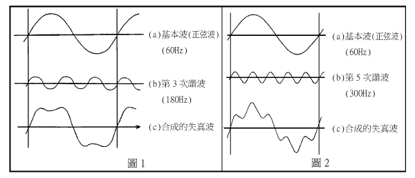
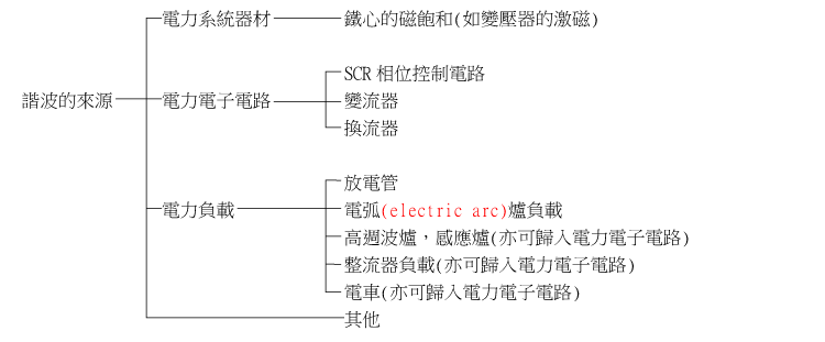
What is a Harmonic?
A harmonic is a waveform whose frequency is an integer
multiple of the fundamental frequency. The combination of
the fundamental wave and its harmonics forms a distorted
wave (as shown in Figure 1 and Figure 2).
Sources of Harmonics [2]
Harmonic Effects on Capacitors and Reactors
Phenomena:
Overload, Overheating, Noise, Vibration.
Failure Modes:
Insulation degradation → Reduced lifespan.
Selection of Reactor Impedance for Series Reactors
[3]
When capacitors are installed in circuits containing
harmonics, a series reactor with approximately 6% impedance
should generally be added.
- For circuits with a high level of 5th harmonic, an 8% series reactor is recommended.
- In environments with significant 3rd harmonic content, such as electric arc furnaces, a 13% or 15% series reactor should be used.
- For circuits where the capacitor is not continuously connected, a 6% series reactor should be installed.
Please refer to the table below for the selection guidelines of series reactors for various major harmonics.
| Harmonic Order | Reactance value selection principle |
| 3rd Harmonic | Typically, a 13% series reactor is used. If the 3rd harmonic content is particularly high, a 15% reactor may be applied. |
| 5th Harmonic |
|
| 7th Harmonic | 6% reactor is typically used. |
| 9th Harmonic | 6% reactor is typically used. |
Taipower's "Provisional Standards for Harmonic Control in Power
Systems" (82/6/5)
(Based on IEEE std. 519-1992)
Harmonic current injected by the user at its responsibility
demarcation point
3.3~22.8kV system
Harmonic current distortion rate (%) limit value
|
|
Individual values of each harmonic (odd order) | Total harmonics |
||||
| Isc/IL | <11 | 11≦n<17 | 17≦n<23 | 23≦n<35 | 35≦n | THD% |
| ﹡<20 | 4.0 | 2.0 | 1.5 | 0.6 | 0.3 | 5.0 |
| 20~50 | 7.0 | 3.5 | 2.5 | 1.0 | 0.5 | 8.0 |
| 50~100 | 10.0 | 4.5 | 4.0 | 1.5 | 0.7 | 12.0 |
| 100~1000 | 12.0 | 5.5 | 5.0 | 2.0 | 1.0 | 15.0 |
| >1000 | 15.0 | 7.0 | 6.0 | 2.5 | 1.4 | 20.0 |
Note
Even-order harmonics are 25% of the above limit.
﹡:Users
with their own power generation equipment shall adopt the limit
value of Isc/IL less than 20.
Isc: Short-circuit current at
the user responsibility dividing point.
IL (r.m.s): Take the
average value of the maximum load current for the existing user
over 12 months.
For new or additional users, take the rated
current value of the main transformer.
For 34.5~161kV
systems, it is 50% of the above limit value.
(Source:
Electrical Engineer 59, pp. 40)